
配置思路
采用以下思路配置:
1.在处于环形网络中的交换设备上配置MSTP基本功能,包括:
a.配置MST域并创建多实例,配置VLAN2映射到MSTI1,VLAN3映射到MSTI2,实现流量的负载分担。
b.在MST域内,配置各实例的根桥与备份根桥。
c.配置各实例中某端口的路径开销值,实现将该端口阻塞。
d.使能MSTP,实现破除环路,包括:
•设备全局使能MSTP。
•除与终端设备相连的端口外,其他端口使能MSTP。
说明:
与终端相连的端口不用参与MSTP计算,建议将其设置为边缘端口。
2.配置保护功能,实现对设备或链路的保护。例如:在各实例的根桥设备指定端口配置根保护功能。
3.配置设备的二层转发功能。
4.配置各设备端口IP地址及路由协议,使各设备间网络层连通。
说明:
本例中SwitchA和SwitchB需要支持VRRP和OSPF,有关VRRP和OSPF的支持形态,请参见相关章节。
5.在SwitchA和SwitchB上创建VRRP备份组1和VRRP备份组2,在备份组1中,配置SwitchA为Master设备,SwitchB为Backup设备;
在备份组2中,配置SwitchB为Master设备,SwitchA为Backup设备,实现流量的负载均衡。
______________________
1,
1.在处于环形网络中的交换设备上配置MSTP基本功能,包括:
a.配置MST域并创建多实例,配置VLAN2映射到MSTI1,VLAN3映射到MSTI2,实现流量的负载分担。
[SwitchA] [SwitchB] [SwitchC]
[SwitchA] stp region-configuration
[SwitchA-mst-region] region-name RG1
[SwitchA-mst-region] instance 1 vlan 2
[SwitchA-mst-region] instance 2 vlan 3
[SwitchA-mst-region] active region-configuration
[SwitchA-mst-region] quit
b.在MST域内,配置各实例的根桥与备份根桥。
c.配置各实例中某端口的路径开销值,实现将该端口阻塞。
d.使能MSTP,实现破除环路,包括:
•设备全局使能MSTP。
•除与终端设备相连的端口外,其他端口使能MSTP。
说明:
与终端相连的端口不用参与MSTP计算,建议将其设置为边缘端口。
c.配置实例MSTI1和MSTI2中将要被阻塞端口的路径开销值大于缺省值
说明:
•端口路径开销值取值范围由路径开销计算方法决定,这里选择使用华为计算方法为例,配置实例MSTI1和MSTI2中将被阻塞端口的路径开销值为20000。
•同一网络内所有交换设备的端口路径开销应使用相同的计算方法。
# 配置SwitchA的端口路径开销计算方法为华为计算方法。
[SwitchA] stp pathcost-standard legacy# 配置SwitchB的端口路径开销计算方法为华为计算方法。
[SwitchB] stp pathcost-standard legacy# 配置SwitchC的端口路径开销计算方法为华为计算方法,将端口GE0/0/1在实例MSTI2中的路径开销值配置为20000,将端口GE0/0/4在实例MSTI1中的路径开销值配置为20000。
[SwitchC] stp pathcost-standard legacy
[SwitchC] interface gigabitethernet 0/0/1
[SwitchC-GigabitEthernet0/0/1] stp instance 2 cost 20000 #让 instance 2的vlan3 走 0/0/4端口
[SwitchC-GigabitEthernet0/0/1] quit
[SwitchC] interface gigabitethernet 0/0/4
[SwitchC-GigabitEthernet0/0/4] stp instance 1 cost 20000 #让 instance1 的vlan2 走 0/0/1端口
[SwitchC-GigabitEthernet0/0/4] quit
-
使能MSTP,实现破除环路
-
设备全局使能MSTP
# 在SwitchA上启动MSTP。
[SwitchA] stp enable
# 在SwitchB上启动MSTP。
[SwitchB] stp enable
# 在SwitchC上启动MSTP。
[SwitchC] stp enable
-
-
-
将与Host相连的端口设置为边缘端口
# 配置SwitchC端口GE0/0/2和GE0/0/3为边缘端口。
[SwitchC] interface gigabitethernet 0/0/2
[SwitchC-GigabitEthernet0/0/2] stp edged-port enable
[SwitchC-GigabitEthernet0/0/2] quit
[SwitchC] interface gigabitethernet 0/0/3
[SwitchC-GigabitEthernet0/0/3] stp edged-port enable
[SwitchC-GigabitEthernet0/0/3] quit
(可选)配置SwitchC的BPDU保护功能。
[SwitchC] stp bpdu-protection
-
将与Router相连的端口设置为边缘端口
# 配置SwitchA端口GE0/0/3为边缘端口。
[SwitchA] interface gigabitethernet 0/0/3
[SwitchA-GigabitEthernet0/0/3] stp edged-port enable
[SwitchA-GigabitEthernet0/0/3] quit
(可选)配置SwitchA的BPDU保护功能。
[SwitchA] stp bpdu-protection
# 配置SwitchB端口GE0/0/3为边缘端口。
[SwitchB] interface gigabitethernet 0/0/3
[SwitchB-GigabitEthernet0/0/3] stp edged-port enable
[SwitchB-GigabitEthernet0/0/3] quit
(可选)配置SwitchB的BPDU保护功能。
[SwitchB] stp bpdu-protection
 说明:
如果与边缘端口相连的是使能了STP功能的网络设备,配置BPDU保护功能后,如果边缘端口收到BPDU报文,边缘端口将会被shutdown,边缘端口属性不变。
说明:
如果与边缘端口相连的是使能了STP功能的网络设备,配置BPDU保护功能后,如果边缘端口收到BPDU报文,边缘端口将会被shutdown,边缘端口属性不变。
-
-
- 配置保护功能,如在各实例的根桥设备的指定端口配置根保护功能
# 在SwitchA端口GE0/0/1上启动根保护。
[SwitchA] interface gigabitethernet 0/0/1
[SwitchA-GigabitEthernet0/0/1] stp root-protection
[SwitchA-GigabitEthernet0/0/1] quit
# 在SwitchB端口GE0/0/1上启动根保护。
[SwitchB] interface gigabitethernet 0/0/1
[SwitchB-GigabitEthernet0/0/1] stp root-protection
[SwitchB-GigabitEthernet0/0/1] quit
- 配置处于环网中的设备的二层转发功能
-
在交换设备SwitchA、SwitchB、SwitchC上创建VLAN2~3
# 在SwitchA上创建VLAN2~3。
[SwitchA] vlan batch 2 to 3
# 在SwitchB上创建VLAN2~3。
[SwitchB] vlan batch 2 to 3
# 在SwitchC上创建VLAN2~3。
[SwitchC] vlan batch 2 to 3
-
将交换设备上接入环路中的端口加入VLAN
# 将SwitchA端口GE0/0/1加入VLAN。
[SwitchA] interface gigabitethernet 0/0/1
[SwitchA-GigabitEthernet0/0/1] port link-type trunk
[SwitchA-GigabitEthernet0/0/1] port trunk allow-pass vlan 2 to 3
[SwitchA-GigabitEthernet0/0/1] quit
# 将SwitchA端口GE0/0/2加入VLAN。
[SwitchA] interface gigabitethernet 0/0/2
[SwitchA-GigabitEthernet0/0/2] port link-type trunk
[SwitchA-GigabitEthernet0/0/2] port trunk allow-pass vlan 2 to 3
[SwitchA-GigabitEthernet0/0/2] quit
# 将SwitchB端口GE0/0/1加入VLAN。
[SwitchB] interface gigabitethernet 0/0/1
[SwitchB-GigabitEthernet0/0/1] port link-type trunk
[SwitchB-GigabitEthernet0/0/1] port trunk allow-pass vlan 2 to 3
[SwitchB-GigabitEthernet0/0/1] quit
# 将SwitchB端口GE0/0/2加入VLAN。
[SwitchB] interface gigabitethernet 0/0/2
[SwitchB-GigabitEthernet0/0/2] port link-type trunk
[SwitchB-GigabitEthernet0/0/2] port trunk allow-pass vlan 2 to 3
[SwitchB-GigabitEthernet0/0/2] quit
# 将SwitchC端口GE0/0/1加入VLAN。
[SwitchC] interface gigabitethernet 0/0/1
[SwitchC-GigabitEthernet0/0/1] port link-type trunk
[SwitchC-GigabitEthernet0/0/1] port trunk allow-pass vlan 2 to 3
[SwitchC-GigabitEthernet0/0/1] quit
# 将SwitchC端口GE0/0/2加入VLAN。
[SwitchC] interface gigabitethernet 0/0/2
[SwitchC-GigabitEthernet0/0/2] port link-type access
[SwitchC-GigabitEthernet0/0/2] port default vlan 2
[SwitchC-GigabitEthernet0/0/2] quit
# 将SwitchC端口GE0/0/3加入VLAN。
[SwitchC] interface gigabitethernet 0/0/3
[SwitchC-GigabitEthernet0/0/3] port link-type access
[SwitchC-GigabitEthernet0/0/3] port default vlan 3
[SwitchC-GigabitEthernet0/0/3] quit
# 将SwitchC端口GE0/0/4加入VLAN。
[SwitchC] interface gigabitethernet 0/0/4
[SwitchC-GigabitEthernet0/0/4] port link-type trunk
[SwitchC-GigabitEthernet0/0/4] port trunk allow-pass vlan 2 to 3
[SwitchC-GigabitEthernet0/0/4] quit
-
- 验证配置结果
经过以上配置,在网络计算稳定后,执行以下操作,验证配置结果。
说明:
本配置举例以实例1和实例2为例,因此不用关注实例0中端口的状态。
# 在SwitchA上执行display stp brief命令,查看端口状态和端口的保护类型,结果如下:
[SwitchA] display stp brief
 MSTID      Port                        Role  STP State       Protection
   0        GigabitEthernet0/0/1DESI  FORWARDING      ROOT
   0        GigabitEthernet0/0/2DESI  FORWARDING      NONE
   1        GigabitEthernet0/0/1        DESI  FORWARDING      ROOT
   1        GigabitEthernet0/0/2        DESI  FORWARDING      NONE
   2        GigabitEthernet0/0/1        DESI  FORWARDING      ROOT
   2        GigabitEthernet0/0/2        ROOT  FORWARDING      NONE
在MSTI1中,由于SwitchA是根桥,SwitchA的端口GE0/0/2和GE0/0/1成为指定端口。在MSTI2中,SwitchA的端口GE0/0/1成为指定端口,端口GE0/0/2成为根端口。
# 在SwitchB上执行display stp brief命令,结果如下:
[SwitchB] display stp brief
 MSTID      Port                        Role  STP State       Protection
   0        GigabitEthernet0/0/1DESI  FORWARDING      ROOT
   0        GigabitEthernet0/0/2ROOT  FORWARDING      NONE
   1        GigabitEthernet0/0/1        DESI  FORWARDING      ROOT
   1        GigabitEthernet0/0/2        ROOT  FORWARDING      NONE
   2        GigabitEthernet0/0/1        DESI  FORWARDING      ROOT
   2        GigabitEthernet0/0/2        DESI  FORWARDING      NONE
在MSTI2中,由于SwitchB是根桥,端口GE0/0/1和GE0/0/2在MSTI2中成为指定端口。在MSTI1中,SwitchB的端口GE0/0/1成为指定端口,端口GE0/0/2成为根端口。
# 在SwitchC上执行display stp interface brief命令,结果如下:
[SwitchC] display stp interface gigabitethernet 0/0/1 brief
 MSTID      Port                        Role  STP State       Protection
   0        GigabitEthernet0/0/1ROOT  FORWARDING      NONE
   1        GigabitEthernet0/0/1        ROOT  FORWARDING      NONE
   2        GigabitEthernet0/0/1        ALTE  DISCARDING      NONE
[SwitchC] display stp interface gigabitethernet 0/0/4 brief
 MSTID      Port                        Role  STP State       Protection
   0        GigabitEthernet0/0/4ALTE  DISCARDING      NONE
   1        GigabitEthernet0/0/4        ALTE  DISCARDING      NONE
   2        GigabitEthernet0/0/4        ROOT  FORWARDING      NONE
SwitchC的端口GE0/0/1在MSTI1中为根端口,在MSTI2中被阻塞。SwitchC的另一个端口GE0/0/4,在MSTI1中被阻塞,在MSTI2中为根端口。
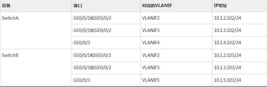
- 配置设备间的网络互连
# 配置设备各端口的IP地址,以SwitchA为例。SwitchB的配置与SwitchA类似,详见配置文件。
[SwitchA] vlan batch 4
[SwitchA] interface gigabitethernet 0/0/3
[SwitchA-GigabitEthernet0/0/3] port link-type trunk
[SwitchA-GigabitEthernet0/0/3] port trunk allow-pass vlan 4
[SwitchA-GigabitEthernet0/0/3] quit
[SwitchA] interface vlanif 2
[SwitchA-Vlanif2] ip address 10.1.2.102 24
[SwitchA-Vlanif2] quit
[SwitchA] interface vlanif 3
[SwitchA-Vlanif3] ip address 10.1.3.102 24
[SwitchA-Vlanif3] quit
[SwitchA] interface vlanif 4
[SwitchA-Vlanif4] ip address 10.1.4.102 24
[SwitchA-Vlanif4] quit
# 配置SwitchA、SwitchB和路由器间采用OSPF协议进行互连。以SwitchA为例,SwitchB的配置与SwitchA类似,详见配置文件。
[SwitchA] ospf 1
[SwitchA-ospf-1] area 0
[SwitchA-ospf-1-area-0.0.0.0] network 10.1.2.0 0.0.0.255
[SwitchA-ospf-1-area-0.0.0.0] network 10.1.3.0 0.0.0.255
[SwitchA-ospf-1-area-0.0.0.0] network 10.1.4.0 0.0.0.255
[SwitchA-ospf-1-area-0.0.0.0] quit
[SwitchA-ospf-1] quit
- 配置VRRP备份组
# 在SwitchA和SwitchB上创建VRRP备份组1,配置SwitchA的优先级为120,抢占延时为20秒,作为Master设备;SwitchB的优先级为缺省值,作为Backup设备。
[SwitchA] interface vlanif 2
[SwitchA-Vlanif2] vrrp vrid 1 virtual-ip 10.1.2.100
[SwitchA-Vlanif2] vrrp vrid 1 priority 120
[SwitchA-Vlanif2] vrrp vrid 1 preempt-mode timer delay 20
[SwitchA-Vlanif2] quit
[SwitchB] interface vlanif 2
[SwitchB-Vlanif2] vrrp vrid 1 virtual-ip 10.1.2.100
[SwitchB-Vlanif2] quit
# 在SwitchA和SwitchB上创建VRRP备份组2,配置SwitchB的优先级为120,抢占延时为20秒,作为Master设备;SwitchA的优先级为缺省值,作为Backup设备。
[SwitchB] interface vlanif 3
[SwitchB-Vlanif3] vrrp vrid 2 virtual-ip 10.1.3.100
[SwitchB-Vlanif3] vrrp vrid 2 priority 120
[SwitchB-Vlanif3] vrrp vrid 2 preempt-mode timer delay 20
[SwitchB-Vlanif3] quit
[SwitchA] interface vlanif 3
[SwitchA-Vlanif3] vrrp vrid 2 virtual-ip 10.1.3.100
[SwitchA-Vlanif3] quit
# 配置主机HostA的缺省网关为备份组1的虚拟IP地址10.1.2.100,配置主机HostB的缺省网关为备份组2的虚拟IP地址10.1.3.100。
- 验证配置结果
# 完成上述配置后,在SwitchA上执行display vrrp命令,可以看到SwitchA在备份组1中作为Master设备,在备份组2中作为Backup设备。
[SwitchA] display vrrp
  Vlanif2 | Virtual Router 1
    State : Master
    Virtual IP : 10.1.2.100
    Master IP : 10.1.2.102
    PriorityRun : 120
    PriorityConfig : 120
    MasterPriority : 120
    Preempt : YES   Delay Time : 20 s
    TimerRun : 1 s
    TimerConfig : 1 s
    Auth type : NONE
    Virtual MAC : 0000-5e00-0101
    Check TTL : YES
    Config type : normal-vrrp
    Backup-forward : disabled
    Create time :2012-05-11 11:39:18
    Last change time :2012-05-26 11:38:58

  Vlanif3 | Virtual Router 2
    State : Backup
    Virtual IP : 10.1.3.100
    Master IP : 10.1.3.103
    PriorityRun : 100
    PriorityConfig : 100
    MasterPriority : 120
    Preempt : YES   Delay Time : 0 s
    TimerRun : 1 s
    TimerConfig : 1 s
    Auth type : NONE
    Virtual MAC : 0000-5e00-0102
    Check TTL : YES
    Config type : normal-vrrp
    Backup-forward : disabled
    Create time :2012-05-11 11:40:18
    Last change time :2012-05-26 11:48:58
# 在SwitchB上执行display vrrp命令,可以看到SwitchB在备份组1中作为Backup设备,在备份组2中作为Master设备。
[SwitchB] display vrrp
  Vlanif2 | Virtual Router 1
    State : Backup
    Virtual IP : 10.1.2.100
    Master IP : 10.1.2.102
    PriorityRun : 100
    PriorityConfig : 100
    MasterPriority : 120
    Preempt : YES   Delay Time : 0 s
    TimerRun : 1 s
    TimerConfig : 1 s
    Auth type : NONE
    Virtual MAC : 0000-5e00-0101
    Check TTL : YES
    Config type : normal-vrrp
    Backup-forward : disabled
    Create time :2012-05-11 11:39:18
    Last change time :2012-05-26 11:38:58

  Vlanif3 | Virtual Router 2
    State : Master
    Virtual IP : 10.1.3.100
    Master IP : 10.1.3.103
    PriorityRun : 120
    PriorityConfig : 120
    MasterPriority : 120
    Preempt : YES   Delay Time : 20 s
    TimerRun : 1 s
    TimerConfig : 1 s
    Auth type : NONE
    Virtual MAC : 0000-5e00-0102
    Check TTL : YES
    Config type : normal-vrrp
    Backup-forward : disabled
    Create time :2012-05-11 11:40:18
    Last change time :2012-05-26 11:48:58
配置文件
-
SwitchA的配置文件
#
sysname SwitchA
#
vlan batch 2 to 4
#
stp instance 1 root primary
stp instance 2 root secondary
stp bpdu-protection
stp pathcost-standard legacy
#
stp region-configuration
 region-name RG1
 instance 1 vlan 2
 instance 2 vlan 3
 active region-configuration
#
interface Vlanif2
 ip address 10.1.2.102 255.255.255.0
 vrrp vrid 1 virtual-ip 10.1.2.100
 vrrp vrid 1 priority 120
 vrrp vrid 1 preempt-mode timer delay 20
#
interface Vlanif3
 ip address 10.1.3.102 255.255.255.0
 vrrp vrid 2 virtual-ip 10.1.3.100
#
interface Vlanif4
 ip address 10.1.4.102 255.255.255.0
#
interface GigabitEthernet0/0/1
 port link-type trunk
 port trunk allow-pass vlan 2 to 3
 stp root-protection
#
interface GigabitEthernet0/0/2
 port link-type trunk
 port trunk allow-pass vlan 2 to 3
#
interface GigabitEthernet0/0/3
 port link-type trunk
 port trunk allow-pass vlan 4
 stp edged-port enable
#
ospf 1
 area 0.0.0.0
  network 10.1.2.0 0.0.0.255
  network 10.1.3.0 0.0.0.255
  network 10.1.4.0 0.0.0.255
#
return
-
SwitchB的配置文件
#
sysname SwitchB
#
vlan batch 2 to 3 5
#
stp instance 1 root secondary
stp instance 2 root primary
stp bpdu-protection
stp pathcost-standard legacy
#
stp region-configuration
 region-name RG1
 instance 1 vlan 2
 instance 2 vlan 3
 active region-configuration
#
interface Vlanif2
 ip address 10.1.2.103 255.255.255.0
 vrrp vrid 1 virtual-ip 10.1.2.100
#
interface Vlanif3
 ip address 10.1.3.103 255.255.255.0
 vrrp vrid 2 virtual-ip 10.1.3.100
 vrrp vrid 2 priority 120
 vrrp vrid 2 preempt-mode timer delay 20
#
interface Vlanif5
 ip address 10.1.5.103 255.255.255.0
#
interface GigabitEthernet0/0/1
 port link-type trunk
 port trunk allow-pass vlan 2 to 3
 stp root-protection
#
interface GigabitEthernet0/0/2
 port link-type trunk
 port trunk allow-pass vlan 2 to 3
#
interface GigabitEthernet0/0/3
 port link-type trunk
 port trunk allow-pass vlan 5
 stp edged-port enable
#
ospf 1
 area 0.0.0.0
  network 10.1.2.0 0.0.0.255
  network 10.1.3.0 0.0.0.255
  network 10.1.5.0 0.0.0.255
#
return
-
SwitchC的配置文件
#
sysname SwitchC
#
vlan batch 2 to 3
#
stp bpdu-protection
stp pathcost-standard legacy
#
stp region-configuration
 region-name RG1
 instance 1 vlan 2
 instance 2 vlan 3
 active region-configuration
#
interface GigabitEthernet0/0/1
 port link-type trunk
 port trunk allow-pass vlan 2 to 3
 stp instance 2 cost 20000
#
interface GigabitEthernet0/0/2
 port link-type access
 port default vlan 2
 stp edged-port enable
#
interface GigabitEthernet0/0/3
 port link-type access
 port default vlan 3
 stp edged-port enable
#
interface GigabitEthernet0/0/4
 port link-type trunk
 port trunk allow-pass vlan 2 to 3
 stp instance 1 cost 20000
#
return
来源:https://www.cnblogs.com/crave/p/10527098.html